Garrattfan's Modelrailroading Pages
NS 6200 class
Superstructure assembly (2)
Well, as I mentioned, things took a long stroll before getting to the point where I picked up activities again. But, what's the rush? Having completed the NGG16 but for the number plates I contacted the fellow modeler who owns a roller bender. He kindly assisted me rolling the boiler. Moreover I had a very agreeable evening visiting his place and workshop. He is a passionate O-scale builder in old English stock. Lovely to see. Do visit his website. Thank you Cor for your help and encouragement!! |
|
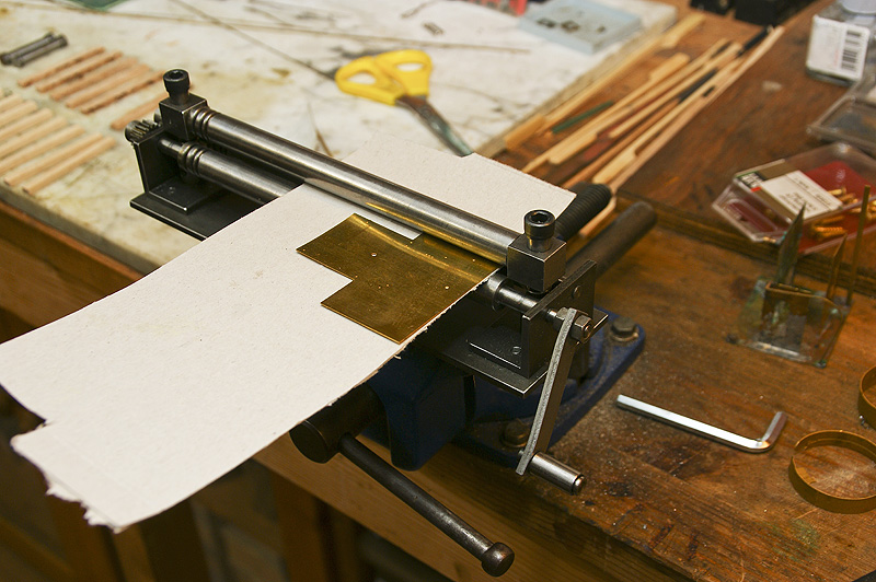
Well this is how it works. Below are two adjacent rolls. On the top center there is third roll which can be adjusted in height. Insert the sheet of metal to be rolled and place it perpendicular to the rolls. Tighten the screws and let's roll!! After some passes the metal curls. Tighten the rolls again and roll. Etc etc. |
|
|
|
|
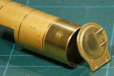
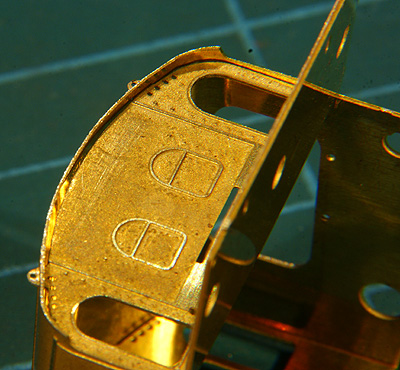
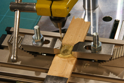
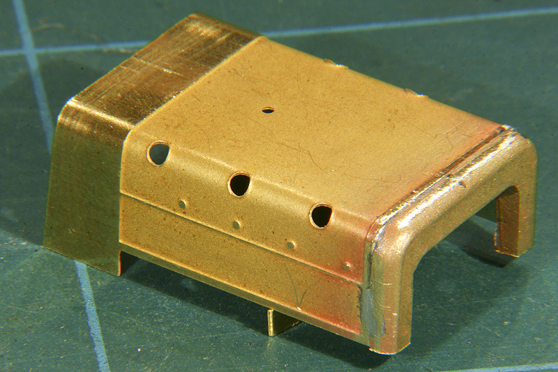
Next thing to be done is to prep the smokebox front. Holes were drilled to accept the hand rails, the lamp support and the smokebox handwheel. |
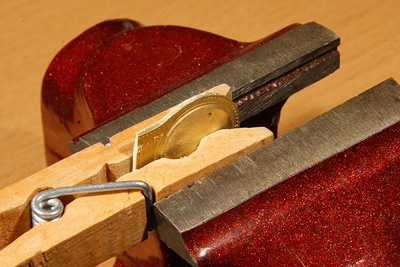 |
The sides of the casting were a little irregular so I carefully filed them. The laundry peg protects the casting from the vise and yet holds the casting firmly |
 |
I can watch a casting like this for hours.
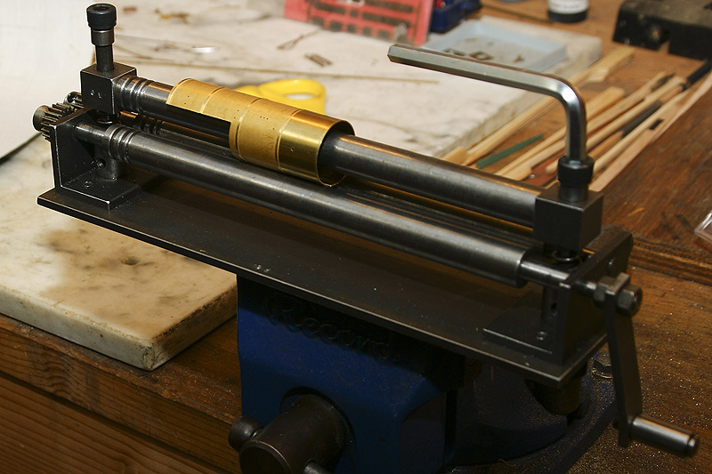
I soldered the boiler joint at the bottom (240C). The boiler forms a shallow V-shape because the last end of the sheet does not "roll" in the roller bender. It seems there is a trick for that but neither Cor nor I knew it, so we accepted the shallow V. It is hardly visible anyway. |
 |
The boiler and smokebox front were joined (188C). I also attached the smokebox wrapper, but I forgot to take a decent photo. You'll see it show up in later photos. |
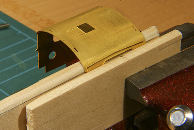 |
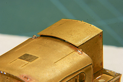
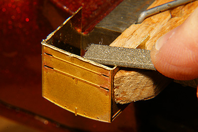
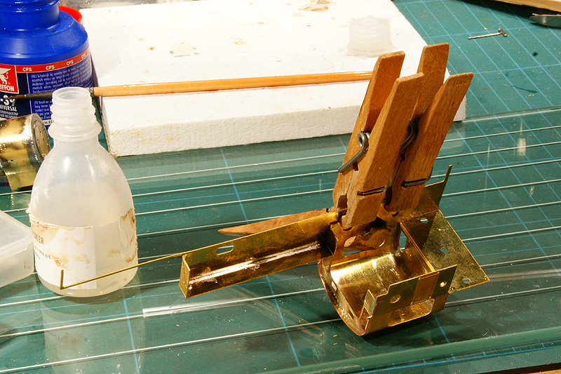
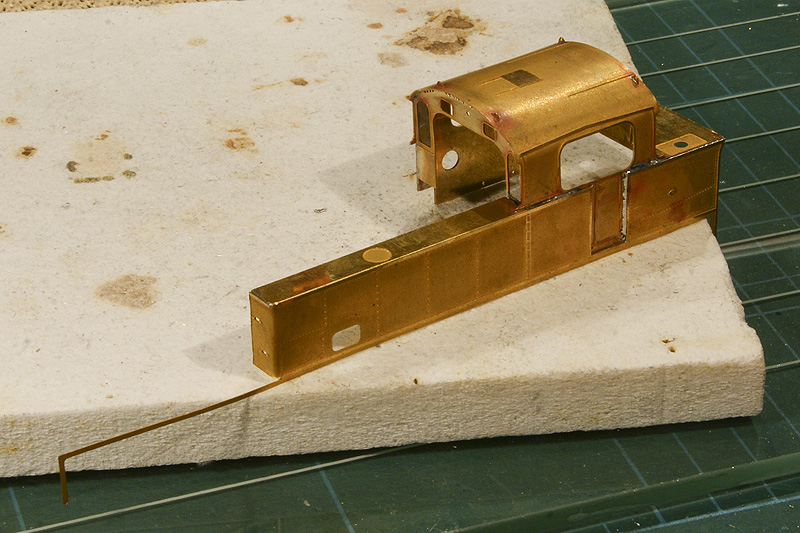
A task that I found very intimidating was forming the cab roof. Rolling the boiler was comparatively easy: the tool did all the work, all you had to do was watch it and check, check, check. Forming the cab roof was an entirely different story: the radius was different at every different spot, very much like a clothoid. I followed Iain Rice's RoBOT technique (round-bar-on-thigh, see "Etched Loco Construction" by Wild Swan Publications). Rolling it on my thigh with a steel bar I gradually formed the easy curve of the mid roof to fit the front and back of the cab. Roll and fit, roll and fit, roll and fit. When it fitted between the slots at the rear, it was time to form the sharper bends at the edges of the roof. I preformed a piece of wood to follow the desired curve. I pre-bent a scrap piece of brass to test fit if the wood had the right shape. Then I bent the roof over this wooden mold. The pencil line on the wood indicates were the bend starts and where it should coincide with the end of the roof overhang flowing into the cab sides. The other piece of wood serves to hold the cab sides in place and also to protect the cab sides from the vise. The result was very encouraging. It fitted to the cab's front and end sheets with little or no persuasion. |
 |
|
 |
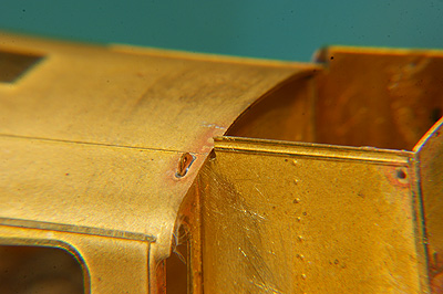
On this photo only a small seam is visible under the roof. With the slightest amount of pressure this seam disappeared altogether. After soldering there was an almost perfect connection. |
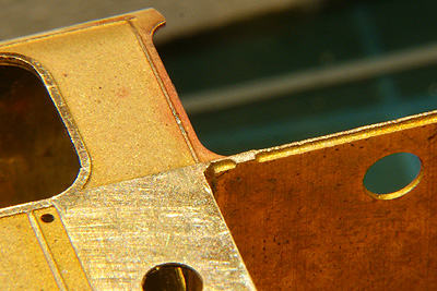 |
Philotrain had the good thought of half etching the solder joints so a very tight more or less V-shaped solder seam would result. Unfortunately there were some etch notches in the half etch which prevented the seam to close neatly |
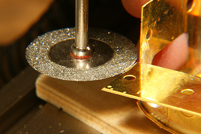 |
I ground them away with the cutting disc. Wear safety goggles! Flying brass particles have tiny wings and are equipped with a full-automatic search and destroy mechanism that is programmed to find your eyes. And be careful, grinding away more than you intend is easier than you think. The cutting disc is waiting to strike!! |
|
|
The solder fillets still need to be cleaned away. |
|
|
|
 |
 |
Coal bunker trouble The NS 6200 originally had a coal bunker below the cab rear windows. In the 1930's an extension up to roof level was added to increase coal capacity. I trial fitted this raised coal bunker. It wouldn't fit. So I enlarged the existing notch on the top to make it fit under the roof. Alarm bells should have rung then. When I tried to fit the coal bunker hatch I realized the whole thing was about a millimeter too high!!
|
|
 |
 |
 |
Making the coal bunker fit by filing alone would be too tedious so I threw some more rigorous tooling into the battle. With the sanding side of a cutting disc this 1 mm oversize was quickly reduced to a few tenths. Be careful though!! The remaining brass was filed by hand. The only problem is the remaining notch.... I filled it with putty. |
 |
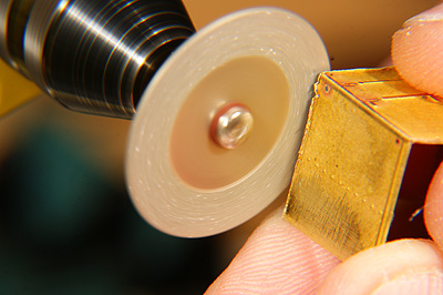
Now I found another problem. I noticed the firebox throatplate (thanks Paul for supplying me the correct English term for it) was substantially narrower, 1.4 mm to be exact, than the corresponding gap in the driver's cab. I questioned my supplier but he responded with an "oops". Then I contacted Philotrain, the manufacturer of the kit, and they reacted rather disturbing. They had outsourced the production of this kit and when a trial run was presented to them they rejected that particular run because of various size deficiencies. A later version was approved. But somehow the rejects where not destroyed and found their mysterious ways to the market as well. I seem to have bought a reject. So I will have to solve the size difference later. |
Colleague builders: BE AWARE. Note: The approved sets are easily distinguishable from the reject as Philotrain always supplies its sets pre-bent and pre-rolled. So the flat boiler, cab roof and firebox are warnings that you buying a reject!! The reject set seems to be cheap, but add the purchase of the cast parts to it and you are still in the range of €200, which is hardly any cheaper than the approved production run which includes the cast parts and has all appropriate parts pre-bent. |
|
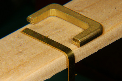 |
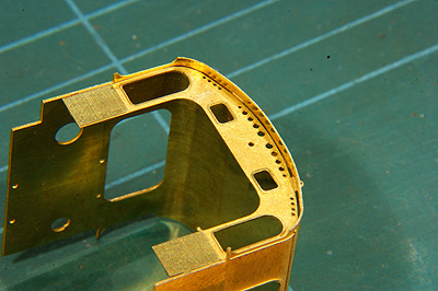
Forming the firebox presented me a new problem. How on earth could I get two bends
As a first step I made a piece of wood exactly the width of the throatplate MINUS twice the brass sheet thickness. I rounded both ends and checked for the correct roundness all over the length of both sides with a piece of scrap brass which I had rounded to match the throatplate's curve |
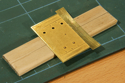 |
I positioned the firebox sheet exactly on the wood (I fixed it with a drop of household glue). Note that I carefully lined up the middle of the sheet with the middle of the wood strip. |
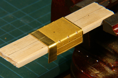 |
Then I bent one side in my vise, like the roof cab with an extra piece of wood to keep the firebox top in place. When I was happy with it did the other side. The result was acceptable, though maybe not as good as I wanted: one side proved 0.4 mm longer than the other side, meaning the centers had been misaligned by 0.2 mm |
 |
But it was good enough. Bending the sheet back, straightening it out and trying it again was a far worse perspective than keeping the plate nice and straight as it was with just that little bit of difference. So what? Not perfect but good enough was my verdict. |
The bends proved to be a little too sharp, they protrude from the corners of the throatplate by 0.25 mm(!). How little this may be, it will still be conspicuous after painting, so I will fill the small space later. |
|
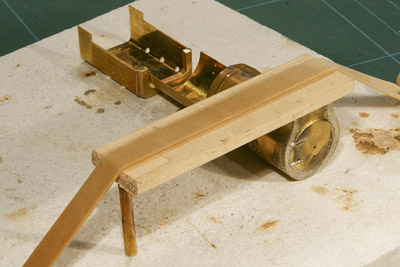
Next job is to join the boiler/smokebox assy to the firebox. A very easy thing to understand, which is more than can be said of many other modelling operations, but also easier said than done. What are the demands?
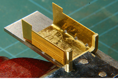
After long consideration I decided to solder the assembly upside down. This way I had the optimum view to align the outer edges of the boiler sheet to the corresponding outer edges of the throatplate. It would also guarantee that both parts would be in line. So the first two demands were met. |
|
|
A lot of words, the photo at the left may demonstrate it much simpler. |
 |
I literally pinned the boiler and the firebox down. Once they were fixed, soldering (188C) was a doddle. This is the reason why I soldered the throatplate to the firebox with 240C (two pics back), I had no heat problems while soldering at 188C |
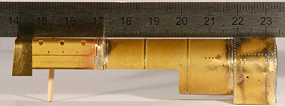 |
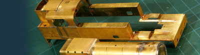
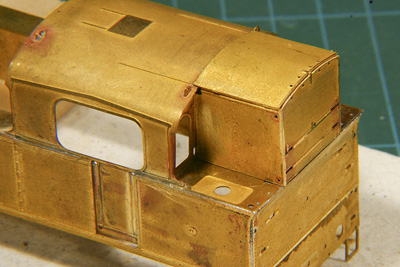
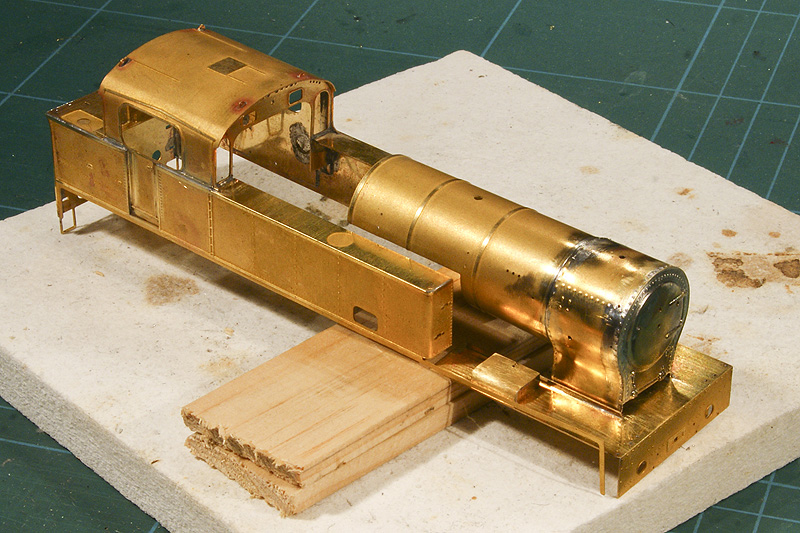
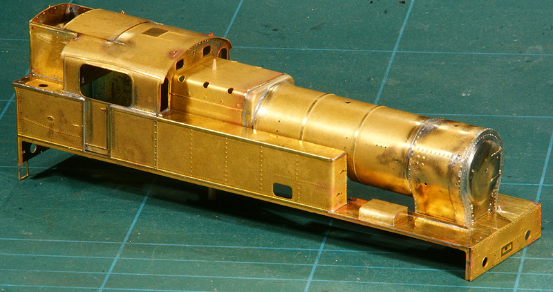
The ruler is the merciless judge of the result. The firebox, boiler and smokebox are in horizontal line within a tolerance of a few tenths of a millimeter. The sunken part of the boiler is lower by design but still almost perfectly parallel. |
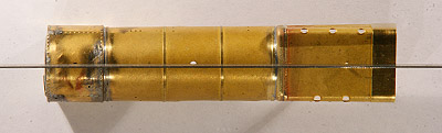 |
The lateral line is even more perfect. The pre-etched holes of stack (left), steam dome (middle) and safety valve (right) show up as a half-circle under the scrutiny of the ruler |
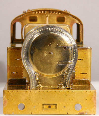 |
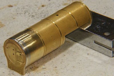
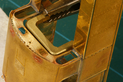
And the final proof of the pudding .... Well, if the firebox is snuggled into the corresponding opening of the cab front, you can see a tiny gap on the (viewer's) right hand side. This is about 0.15 mm (I actually tried to measure it with my caliper). Although I hoped for a more accurate result, it nothing serious. The gap will fill with solder, the detail parts on the boiler will need a tiny correction to the right side and no one will be able to see with the naked eye that the boiler is a teeny weeny bit off. |
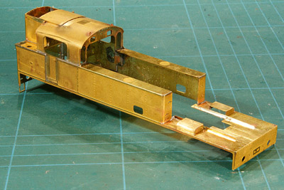 |
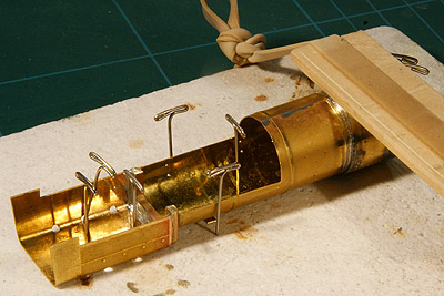
Now I joined the front part of the footplate to the rest of the loco (188C). That is a bit tedious because there is very little to hold to when soldering. Again soldering upside down on the soldering pad and providing adequate support of the part to be soldered did the job. But the good news: at last I got rid of those nasty always-in-harm's-way protruding etched ends that now are soldered safely below the footplate |
I must admit I am a little proud of my work |
|

Sign my
GuestBook